Valve renovation guarantees headrace safety at Kühtai pumped-storage hydropower plant9 min read
Lesedauer: 6 MinutenThe mighty DN3500 valves were in operation in the headrace at the Kühtai pumped-storage hydropower plant for around 40 years. When the Tyrolian plant operator TIWAG lowered the level of the adjoining reservoir in the late autumn of 2019, it provided a perfect opportunity for a fundamental maintenance sweep of the headrace. Particular attention was paid to restoration of the two PN25 pressure category butterfly valves. The work was conducted by Geppert, the Tyrolian hydropower specialists. The contract posed several technical challenges and took around half a year to complete.
The Längental and Finstertal reservoirs form the hydraulic basis for the Kühtai pumped-storage hydropower plant, part of the Sellrain-Silz group under the auspices of Tiroler Wasserkraft AG (TIWAG). The reservoirs are connected via a DN3500 pipeline. Safety is ensured along the works water route by two mighty butterfly valves installed in a cavern-like service chamber at over 2,150 metres above sea level, directly under the Finstertal reservoir dam. The valve service chamber can only be accessed via a 300-m tunnel in the mountain. At the beginning of 2020 there was an ideal opportunity to subject the valves of the works water pipeline to a comprehensive programme of restoration. Hugo Götsch, the TIWAG project manager, commented on the initial situation: “At first there were no external signs of wear or damage to the valves, but when the decision was made to empty the reservoir, we seized the opportunity to inspect these essential shut-off devices – and repair them if required. Fortunately, the drawdown of a reservoir is a fairly rare occurrence.” Geppert Hydropower, the Tyrolian hydropower allrounders, were charged with the refurbishment of the two valves, the bottom outlet infrastructure, the dead space draining system and of the regulating gates.


Comprehensive preparations
Before deinstallation could commence in the valve service chamber there were several issues in need of attention, as Markus Klotz of Geppert Hydropower remarks: “Along with the necessity of scheduling work, equipping the site, organising assembly teams and coordinating with the various subcontractors, it was first necessary to plan dismantling work. This involved a carefully-sequenced task framework. Moreover, we needed to agree points of contact with the TIWAG team, and establish in advance how much leakage water could be expected from the bottom outlet. This was important because a large degree of leakage would have necessitated a different sitework plan, and it wouldn’t have been possible to remove both valves simultaneously. We would have had to remove them one after the other.” Activities ultimately commenced in January 2020 when Geppert began dismantling the original valves. This was no easy task, since each of the 3.5-m valves weighed around 60 tons. Luckily the assembly team had access to the original plant installation plans from 1979. This allowed dismantling to be conducted as an exact reversal of the original installation procedure. Nevertheless, both the dismantling work, and subsequent transportation of the individual components out of the access tunnel, involved considerable technical challenges.
Challenging dismantling process
Geppert’s Markus Klotz explained the main steps in the dismantling process: “First, the dismantling team had to remove all attachments, such as the bypass pipes, measuring conduits and supply channels, the parts of the drive systems on both sides, hydraulic cylinders, drive levers and counterweights. Subsequently we loosened the flanges of the dismantling joint to provide an axial gap of around 12mm. This enabled us to move the downstream side valve on a purpose-built track towards that gap and to lift the intermediate pipe out of its position. Having relieved the disc’s weight with assembly supporters, the technicians were able to remove the first half of the housing sideways. Subsequently, the disc was removed from the remaining half of the housing.” Once dismantled and removed, the components were prepared for transportation. The procedure was performed in the same way for the dismantling of the upstream side valve.


Handling heavy weights
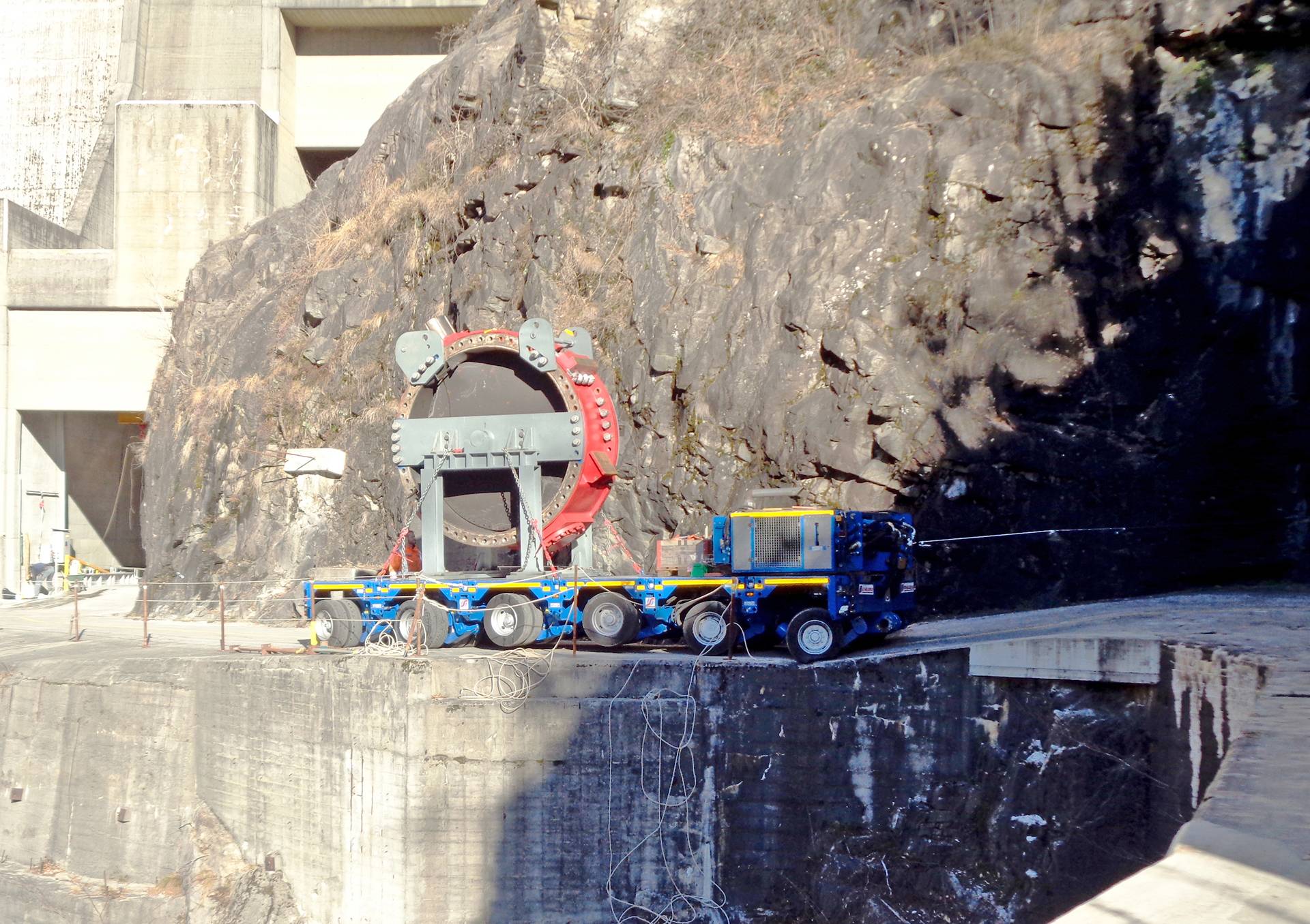
TIWAG’s overhead hall crane had already been upgraded to a maximum capacity of 30 tons ahead of transportation to enable it to lift the 25-ton valve discs and the trunnions. Transporting the items along the access tunnel was a first test for the viability of the operation. Due to the cramped conditions, as soon as each individual component had been removed from the overall set-up it was transported out through the tunnel. “Since the system was originally built, the size of the tunnel cross-section had shrunk by the height of the road. As a result, components that couldn’t be disassembled any further, like the intermediate pipe and the dismantling joint, had to remain in the valve chamber to be refurbished there. For this reason, special tunnel ventilation had to be installed for cor- rosion protection work” Markus Klotz explained. He emphasised the need for extremely detailed planning regarding transportation of the valve parts out of the tunnel. This required very precise cross-sectional measurements of each section of the uncladded tunnel, the aim being to facilitate transportation of components, such as the housing parts and the valve discs, out through the tunnel using a manoeuvrable heavy-duty trailer. Klotz continues: “We developed a support frame to transport the valve discs with the trunnions attached. So the adapted heavy-duty trailer was able to manoeuvre its bulky load along the tunnel, and then a special heavy-load transport convoy to the factory in the town of Hall, without exceeding an effective width of 3 metres.”
On top of the technical difficulties encountered in the cramped valve service chamber, Geppert’s team of technicians were also confronted with the challenges of an Alpine winter. Hugo Götsch outlined the scenario: “In January 2020 it was mid-winter up there at 2,000 metres above sea level, and the snow was around 1.50 metres deep. Fortunately, however, the weather was good.” Under these conditions it was still possible to use a mobile crane to load the components onto AWD articulated vehicles that drove down the toboggan run to Kühtai, cleared of snow for this special purpose, and the along the Sellraintal valley to Geppert’s factory in the town of Hall.
Damaged trunnions
Once the old components had arrived at Geppert’s works halls they were subjected to detailed inspections. Geppert’s specialists worked together with the experts from TIWAG to identify damage to parts and comprehensively document their current state. The inspection process also involved 3D measurement scans of the positioning and orientation of the valve discs and trunnions in relation to each other. This revealed corrosion damage in numerous places at the hard chromium plating of the trunnions. Markus Klotz outlined a further technical obstacle: “Under these circumstances there was no alternative but to remove the trunnions from the valve discs. The thermically pretensioned bolts that had been used to affix the trunnions to the valve discs had to be warmed up with purpose-built heating rods in order to loosen the round locking nuts that had become particularly difficult to move due to the build-up of dirt and corrosion.”
Once the trunnions had been dismantled the remaining bolts in the valve disc were removed. The 600-mm chrome-coated trunnions were then machined on the factory’s own turning machine, and all surfaces and materials were checked for cracks. A fortifying tungsten carbide coating was applied to the surfaces where the bearing is in contact. “In contrast to simple chrome-plating, this coating is designed to cope with stress and wear far longer” Hugo Götsch adds.
Restoration of steel components
The valve discs were subjected to thorough non-destructive testing after the sandblasting process. “All of the relevant cracks and damaged areas were ground down and a special filler applied to key points. Then the anti-corrosive protection layer was renovated in our own sandblasting facility and our paint application chamber. The profile sealing on the edges and surfaces of the valve discs, as well as all sealing elements on the bearing points, were all renovated” stated Markus Klotz. Following the original assembly instructions, the trunnions were mounted to the valve discs with thermically pretensioned bolts. Correct orientation of the trunnions to the valve disc was analysed in 3D again, set and verified. After sandblasting, as with the valve discs, the halves of the housings were also subjected to non-destructive testing – and all significant cracks were ground away. The existing stopper points for the valve discs were milled down and rewelded. Superficial corrosion was filled-in and then coated with an anti-corrosive protection layer. Subsequently, the hollow spaces were sealed off and all threads were recut.
Reinstallation of restored components
The cramped conditions in the valve service chamber meant the restored components had to be delivered and reinstalled individually, and this depended upon the speed of assembly. The bolts with dimension M110 for connecting the housing halves were replaced completely. In contrast to the original hot bolting, the connection was pretensioned with multiple new threaded screw elements. “In the course of reinstallation, all seals, hydraulic power units, all hydraulic supply pipes, greasing of the trunnions, a variety of pressure gauges and the whole sensor system was renovated or replaced” says Markus Klotz. Once the upstream side valve had been mounted again, it was possible to authorise a leakage test in the works water pipeline and to reopen the reservoir intake. Finally, the intermediate pipe, the downstream side valve and the dismantling joint were installed, rendering the works water pipeline operationally ready again. Geppert completed the maintenance and refurbishment procedures by renewing the shut-off valves of the DN1000 bottom outlet, and the DN350 closure slides for dead space draining. In addition, the operational and protective gates at the bottom outlets of both reservoirs were improved, and the hydraulic power units, hydraulic cylinders, all seals and all anti-corrosion sealing renewed.
Re-Commissioned after six months
The technical challenges were compounded at this time by Corona lockdown restrictions. This played a key role in the progress and procedures during the entire project phase. “We had a very effective hygiene plan for the construction site. In fact, we didn’t have a single case of Corona” Hugo Götsch recalls. Overall, he awarded top marks to the project partner, Geppert, and for the successful management of the project. Since such opportunities to work in the works water conduit are fairly rare, extreme care and supreme working standards were essential. These were qualities the Geppert project team most certainly brought to bear. Following completion of the 6-month maintenance period, detailed analyses and optimisation activities enabled tests at higher flow rates than the original tests for commissioning had been. Finally, with all tasks completed, TIWAG put the pumped-storage power plant back online.
Share: