
Hydraulic Optimization and Model Testing for the Refurbishment of a Vertical Kaplan Turbine
Bild: © Jaberg & Partner
A few years ago, Jaberg & Partner was commissioned by Flovel Energy to develop a new vertical axis Kaplan runner and new guide vanes for the rehabilitation of a run-off-river power plant located in a diversion channel in the state of Uttarakhand in the north of India. After an optimized turbine design was developed based on a comprehensive CFD-study, a model test was performed in order to be able to experimentally verify the excellent performance. In the meantime, the first two units were successfully commissioned and are running to the customer‘s full satisfaction. The field acceptance test was conducted at Unit 1, attesting to the satisfactory performance of the turbine. The third unit is in the final stage of assembly and will be commissioned in the mid of 2026. This publication provides an overview of the successful progress of this refurbishment project.
Kaplan Turbine Rehabilitation Based on CFD Optimisation
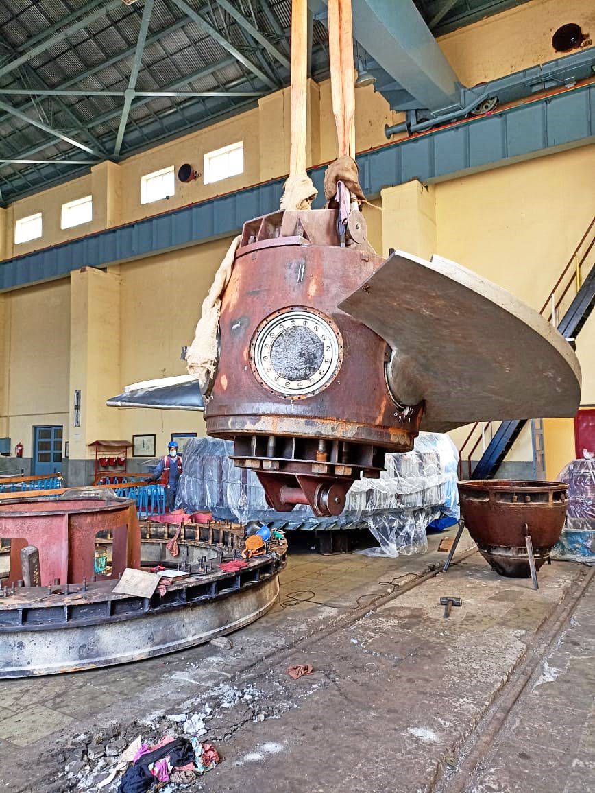
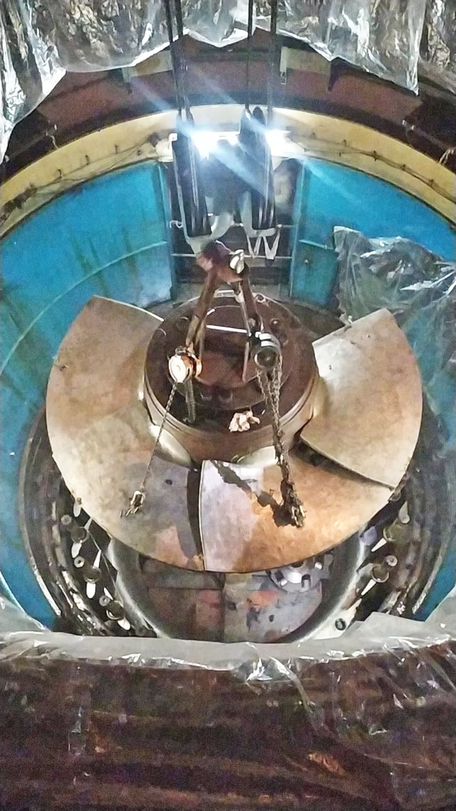
The power plant comprises 3 vertical Kaplan units and was originally commissioned in 1965. After an operating time of around 60 years, the turbines were in relatively poor condition, which is shown with the photographs of the turbine dismantled on site (see Figure 1). Furthermore, the lack of efficiency and the limitation of the maximum flow rate required an optimization of the turbine components.
Corresponding to the submitted project data, the hydraulic recalculation and optimization, model design and a model test according to IEC 60193 were requested.
For this purpose, reverse engineering of the existing water passages was carried out using scanning technology of surfaces at site and original drawings as reference only. A 3D drawing of water passages for CFD simulation purpose was prepared and checked to ensure the reproduction of existing passages within the hydraulic tolerances defined in IEC 60193. The runner blade geometry was then optimized by applying Computational Fluid Dynamics (CFD), using ANSYS CFX.
The number of runner blades accounts for zRu = 6, while the number of guide vanes is zGV = 24 – both needed to be retained in course of the optimization process. The runner diameter, which had to be unaltered as well, accounts for D = 3.4 m, and the turbine speed was fixed with n = 187.5 rpm. Furthermore, it’s worth mentioning, that the original turbine has a quite high hub-ratio ν = DHub/DShroud of 0.47, which was reduced in course of the optimization process. Referring to the rated net head of H = 19.6 m, the target was to achieve a weighted averaged efficiency of ηWAE = 93%.
According to the given specifications, the specific speed nq of the turbine is calculated as:
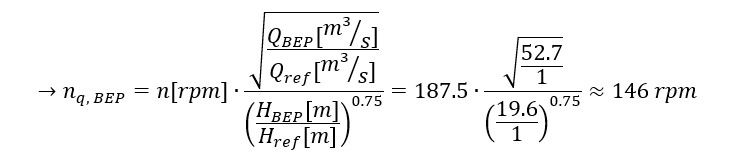
Kaplan-turbines with a specific speed of nq,opt = 146 rpm are typically equipped with 4 or 5 runner blades. The comparatively high number of runner blades was probably chosen because of cavitation reasons. By using the critical suction head HS = -0.65 m (valid for the single unit operation) and the altitude of the power plant, the critical cavitation coefficient (also Thoma-No.) of the plant σ PLANT accounts for only 0.52.
At the beginning of a rehabilitation project, verifying the overall design parameters of the turbine to be optimized is generally quite helpful. For this purpose, various design guidelines were used to check the main turbine dimensions given for the plant. The analysis showed, that a slightly lower runner diameter of D = 3.25 m (~ 5% smaller than given), a lower hub-ratio of ν = 0.42 (~ 10% smaller than given), but slightly higher guide vanes with b0 = 1.3 m (~ 5% higher than given) would be used, if the turbine would be built from scratch with the same speed of n = 187.5 rpm. Furthermore, to maximize the turbine efficiency, it would obviously have been better to build a slightly smaller unit with a lower number of runner blades (zRu = 5 instead of zRu = 6). Due to these geometric restrictions, the development process presented a number of challenges.
© Jaberg & Partner
CFD Optimisation and Model Development
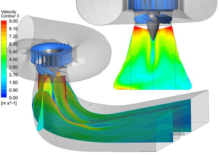
Within a time period of around 3 months, a completely new runner and distributor were developed by applying CFD. Figure 2 present some impressions of the velocity- and pressure-distributions plotted on the runner blades and on cross sections in the draft tube for full load conditions of the optimized turbine.
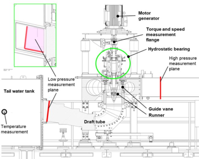
In parallel to the optimization process, the design of the model turbine was created. An overview of the model installed at the test rig is presented with Figure 3. The model test of the optimized turbine was performed at the Institute of Hydraulic Fluidmachinery at Graz University of Technology.
© Jaberg & Partner
The focus of the measurements was primarily on proving the guaranteed efficiency levels and the cavitation safety. Furthermore, the design-relevant adjustment torques of the guide vanes and runner blades had to be measured, which mainly occur in off-design conditions.
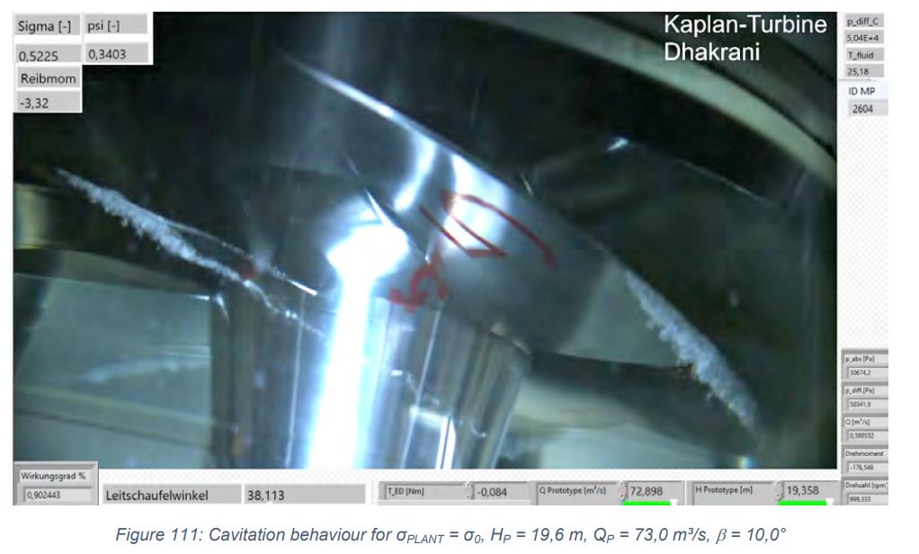
Cavitation tests were primarily performed at operation points relevant for high load operation with 1, 2 and all 3 units. These tests included efficiency-drop-curves and visualizations of the flow patterns – see Figure 4 as an example. It shows the tip clearance cavitation occurring at high load operation conditions at the critical cavitation coefficient of the power plant.
© Jaberg & Partner
After the completion of the measurement campaign and the evaluation of measurement data, a comparison of the turbine performance calculated by means of CFD and found in course of the experimental study on the test rig was prepared.
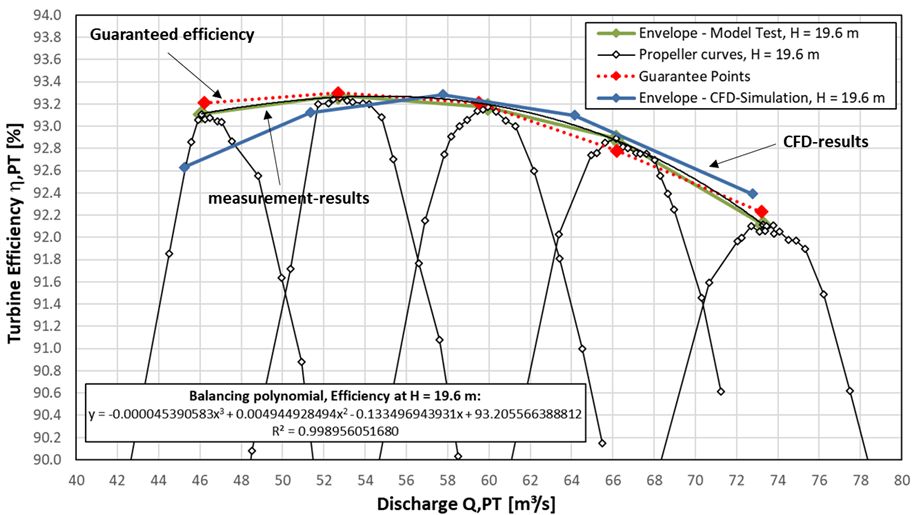
Referring to the nominal head of H = 19.6 m, Figure 5 presents a comparison of the simulated and measured turbine efficiency over the entire range of operation. Additionally, the guarantee points are marked with a red curve. Especially at high-load operation conditions, the comparison shows an excellent correlation of CFD- and measurement-results. Compared to the measured and guaranteed values, the efficiency calculated by applying numerical methods is slightly lower at part load conditions and slightly higher at full load conditions. Finally, the model test has proven that the guaranteed weighted efficiency of 93.0% is exactly achieved. Moreover, the promising results were also proven in course of a field acceptance test on the first unit.
© Jaberg & Partner
Manufacturing and Installation of the New Kaplan Turbine
After the model test results were accepted and approved by the end customer and operator of the power plant, the prototype construction work and manufacturing of the new turbine components started.
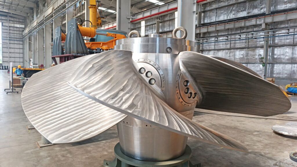
The new Kaplan-turbine was entirely manufactured in India and Figure 6 gives an impression of the new customized 6-blade runner design after the pre-assembly.
© Jaberg & Partner
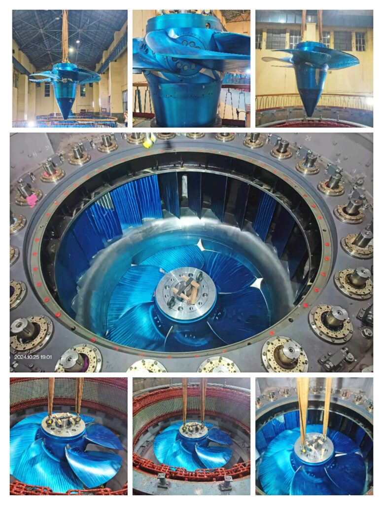
Moreover, Figure 7 presents a photographic record of the installation of the new turbine in the plant. At the end of 2025 the second unit was successfully commissioned. The third unit is in the final stage of assembly and will be commissioned in the mid of 2026.
© Jaberg & Partner
Authors
- Schiffer, J.1, Benigni, H.2, Devinar, L.3
- 1 Jaberg & Partner GmbH, Kerscheckstraße 41, 8076 Vasoldsberg, Austria
- 2 Institute of Hydraulic Fluidmachinery, Graz, University of Technology
- 3 FLOVEL Energy Private Limited, Faridabad/India
- Corresponding Author: Jürgen Schiffer, juergen.schiffer@jabergundpartner.com
- Phone: +43 660 104 58 14